Lifting Lug Design Spreadsheet Calculator. Flag for inappropriate content.

Lifting Lug Calculation Pdf Stress Mechanics Bending
Handling The cask is designed to be supported on the two pairs of the trunnions during the.
. Min Ult Strength is 6 times the working load limit. Ford 2005 e 150 owner s manual pdf download. The following load cases have been addressed.
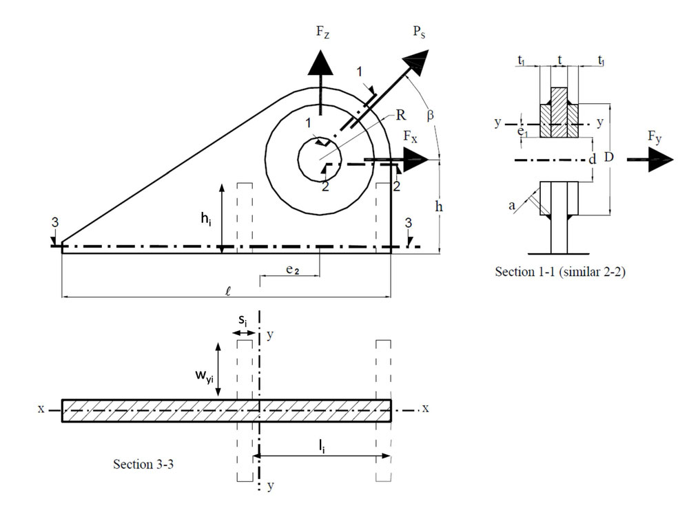
Lug thickness Lug pad thickness Angle of lifting Lug length at bottom Lug hole diameter Lug outside radius Lug pad length Height of Lug hole Lug pad width. Lifting points to provide adjustable lifting centres to handle out of balance loads to remove or control inward or crushing forces to allow for special load attachments. A lifting beam can also be used as a strong back to provide multiple lifting points on a relatively flexible object See Fig.
Pressure vessel design calculations. Max proof load is 22 times the working load limit. Ordinary Lift Plan Elements Once a lift has been planned and approved the appropriate rigging equipment.
DesignEvalution of Overhead Lifting Lugs Page 5 f1 W Based on Ref. PLATE LUG DESIGN WITH A SIDE LOAD Maximum Reach. The design of lifting lugs involves a Hertz stress problem as relates to the bearing btwn.
83 6 83 found this document useful 6 votes 12K views 3 pages. Lifting Lug Calculation Pdf. The hole is sized to fit a clevis pin.
Lets say the lift is vert then the pin is in bearing at 1200 noon. The pin and the lifting lug pl. Engineering Excel Spreadsheet Downloads Welding Design and Engineering Pressure Vessel Design and Engineering.
The dynamic factor depends on the means used for the lifting. 5 Calculations 501 Shear plane locating angle Locates the two planes along which shear tear out occurs. Cv mechanical engineer static equipment amp piping pressure.
DESIGN LOAD PER LIFTING LUG Ph DESIGN LOAD PER LIFTING LUG Pvert Nominal Shackle Size in Working Load Limit kips L N P Crosby Forged Anchor Shackles G-2130 S-2130 Dimensions in Note. Www excelcalcs com AISC Lifting Lug. DYNAMIC FACTOR When the movement of the precast unit is performed by lifting gear dynamic forces that depend on the lifting gear used appear.
Research Paper DESIGN AND BUCKLING STRENGTH. Save Save Lifting lug calculationxls For Later. As discussed in Reference 1 using a factor of 18 on AISC allowables results in a factor of safety of 5 for A36 steel.
Lifting factor f is the acceleration factor. Lifting lug design usa air force method kezar engineering. Class is determined by the selected lifting system for example class H1 for a bridge crane class H4 for a fork-lift truck on an uneven ground.
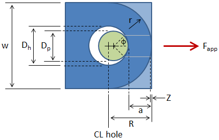
Abstract This supporting document details calculations for the proper design of a lifting beam and redesigned lifting lugs for the 241AZ01A decant pump. Ratio of the pin to hole diameter such that a loose fitting pin has a smaller shear plane than a tight-fitting pin Half angle of the portion of the pin in contact with the lug Ref 2 eq 9 phi d 55 Dp Dh 44815 502 Design Factor and. Lifting Lugs Design Calculations Lifting Beams calculation tony tay Academia edu.
S106pdf - Read File Online - Report Abuse. Otherwise the various vessel books as mentioned. Darbury Lifting Lug Operating Document.
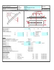
ASME BTH is not a required code for lifting lugs but some of the design checks in it can be applied directly to lifting lugs so it is a useful reference despite the lugs not fitting the exact scope of the standard. Wi z N kg 125 2. Lifting Lug Design Spreadsheet Calculator.
For mechanical static equipment these lifting lugs are used by cranes for transportation and installation. Coverdel 1 Signature OrganizationCharge Code SAE18146 7. Lifting Beam Lifting Lug Analysis 241AZ01A Decant Pump 6.
As the term specifies lifting lugs are used for lifting. Lugs are connector type elements used as structural supports for pin connections. Attribution Non-Commercial BY-NC Available Formats.
It is possible to buy standard models or to manufacture them yourself with sheet metal. AISC Code Checks per Section D32. A Lifting lug is a plate with a hole in it.
Lifting Lug WRC Calculation Ideametrics Private Limited. The lifting classes are described in DIN 15018. Download as XLS PDF TXT or read online from Scribd.
The Checklist for Lift Planning and Weather Factors exhibits found in the Lifting Safety Subject Area as tools for evaluating the area of operation and potential. Calculations to be made will include the capacity both of the overall beam and of the loading of the individual lifting points. Stress being tension in the regions btwn.
When lifting and carrying precast elements the lifting load has to be multiplied by the f factor. DesignEvalution of Overhead Lifting Lugs Page 7 1. Using lifting lugs combined with the clevis pins loads are transferred from one mechanical component to another.
Design Calculations Deisohexanizer Reboiler E-610 29 July 2010 Revision. FEA lugs pin margin of safety Vonmises stress ANSYS. AD-MERKBLAETTER 2000 11-2007 Karman Effects Prevented by 3 Helicoidal Plates at 120.
When lifting and carrying precast elements the lifting load has to be. This is in line with ASME B3020 which requires a design factor of 3 on yield strength and ANSI N146 which requires a design factor of 3 on yield strength and 5 on ultimate. 4A Some lifting beams are made with a bottom lug aligned directly below the top lug so that if the need arises an occasional straight pick can be made without the inconvenience of having to remove the lifting beam.
1 LIFTING LUG DESIGN CALCULATIONB SCHEMATIC DIAGRAM OF 2 NOS LUGS WITH NO TAILING LUGC2Cz2Cx2COGW dsgqHcgHllHcgcos. Download PDF - Lifting Lug n92qjqn73pwp. Com LIFTING LUG DESIGN DATA - Total empty weight - Safety Factor - Number of Lifting Lug SKETCH OF LIFTING LUG.
Lifting The loaded cask is lifted using the two upper trunnions as shown in Figure 1. A lifting lug is a lifting and handling accessory generally welded to a part to hoist it with a crane overhead crane hook. DesignEvaluation of Overhead Lifting Lugs should be used for the calculation of tensile capacity a eff.
That the trunnion design meets the applicable requirements of 10 CFR Part 71 Reference 2. This is just one of the solutions for you to be successful. A lug also known as a lifting lug is essentially a plate with a hole in it where the hole is sized to fit a clevis pin.
104962 Microprotol 32905 - Jul 2010 procal V32905 - 01072010 8 prodia2 V32905 - 1072010 EuResearch Input data list Design Parameters. Lifting calculation method 3. Lifting lug design calculation list of codes amp standars piping study.
Design calculations for lifting lug welded onto equipment like pressure vessels etc. And they involve a combined stress problem with the max.
Lug Analysis Mechanicalc
2
Design And Verification Of Lifting Lugs Mec Engineering Spreadsheets
224993828 Lifting Lug Calculation Pdf Project Dorad 800 Mw Combined Cycle Power Plant Top Great Engineering Marine Pte Ltd Client Item Course Hero

Lifting Lug Design With Example What Is Piping

Lifting Lug Design With Example What Is Piping

Lifting Lug Design With Example What Is Piping

Design And Verification Of Lifting Lugs Mec Engineering Spreadsheets
0 comments
Post a Comment